Development
Email controlled Christmas tree
At Mailjet, we decided to put together a Christmas tree that has lights and an LED dot matrix that is controlled via email through our inbound email API

PUBLISHED ON
Ho ho ho! 'Tis the season to be jolly and give. Not only this, but 'tis also the season to build some dope Christmas themed hardware! Here at Mailjet, we decided to put together a Christmas tree that has lights and an LED dot matrix (acting as the star on top) that is controlled via email through our inbound email processing API - Parse API. Want the lights to be blue? Email christmas.tree@mailjet.com with the commands and it will change! Want a beautiful gold star displayed on the dot matrix at top? Email that in the subject line and it will update!
In this post, I'm going to give a step by step guide for amateurs in the hardware game on how to wire the components, upload the software, and have a fully functioning email controlled Christmas tree of your own.
Table of contents
03
Software
Wiring
LED Strip
LED Dot Matrix
Powering
The breadboard - solderless vs permanent PCB
12
El fin
Want to see one in action before making one of your own?
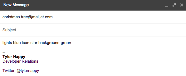
Hop over to our site for the live feed and a list of current commands. Email your commands to christmas.tree@mailjet.com and watch as it applies your updates in real-time. Here's an example of how to send your commands:
What you'll need
Hardware Here is a list with all of the links where to purchase:
1 2ft Christmas tree (obviously)
2 meters of Adafruit NeoPixel Digital RGB LED Strip - White 30 LED (length will change depending on size of tree)
1 LED dot matrix (Medium 16x32 RGB LED matrix panel)
1 Female DC Power adapter - 2.1mm jack to screw terminal block
1 USB A/Micro B (one comes with Spark Core)
Many jumper wires (male-male and male-female)
1 Breadboard (comes with Spark Core)
1 rubber band (to keep LED dot matrix on top of tree)
I purchased all of my components from Adafruit. They are super reliable and provide libraries for most of their hardware and breakout boards.
I purchased the Christmas tree on Amazon. I choose a 2ft tall one, seeing as it would be in an office. For this height, I figured 2 meters should suffice. Also, I found that 30 LEDs per meter was a good amount for this height. If you wish to have more lights on your tree, I would get the 60 LEDs per meter strip . Keep in mind, this will increase the total cost of your project.
The microcontroller I used is the Spark Core. The reason I picked the Spark Core is that it is Arduino-like and has a built-in WiFi module. To access the Spark Core via WiFi, all you have to do is declare a function, the endpoint to call it at, and Spark Core will execute this function when a POST request is done to the endpoint. It's super easy, very efficient and so, it was the logical choice for this particular project.
Once you get your Spark Core, head on over to their getting started page. This will give you a brief overview on how to use it. Essentially, you will need to make an account and connect the Spark Core to your local WiFi. Having the Spark Core connected to WiFi is essential for this project, so make sure this is working before beginning.
After acquainting yourself with the microcontroller, go to their Web IDE. There, you will find two essential codes you will need to communicate with the Spark Core - your "Device ID" and your "Access Token". Without these, you will not be able to change the lights on the tree.
Software
You'll need four essentials:
A Mailjet account to create an instance of the Parse API to receive incoming messages
A server to accept POST requests (In this tutorial, I use Ruby on Rails. If you don't already have Ruby on Rails installed, I would check this page out. Remember, you can use any type of server so long as it can accept POST requests and make POST requests.)
Ngrok for local tunneling to host your server on your computer
The Spark Core libraries for the LEDs and the dot matrix
I have consolidated all of the software you need in this Github repository so you can get your tree up and running as quickly as possible. Simply clone the repo, initiate Mailjet's Parse API, get the server up and running, and upload the software to the Spark Core.
How everything will interact
You may be asking yourself how this whole thing will play out in real-time. We will essentially have four pieces of technology interacting with each other, much like a game of telephone. One piece gets information from the previous, manipulates it a bit to make it easier for the next piece of technology to understand, and then dumps this data onto the next piece, all the way until we have LEDs changing colors!
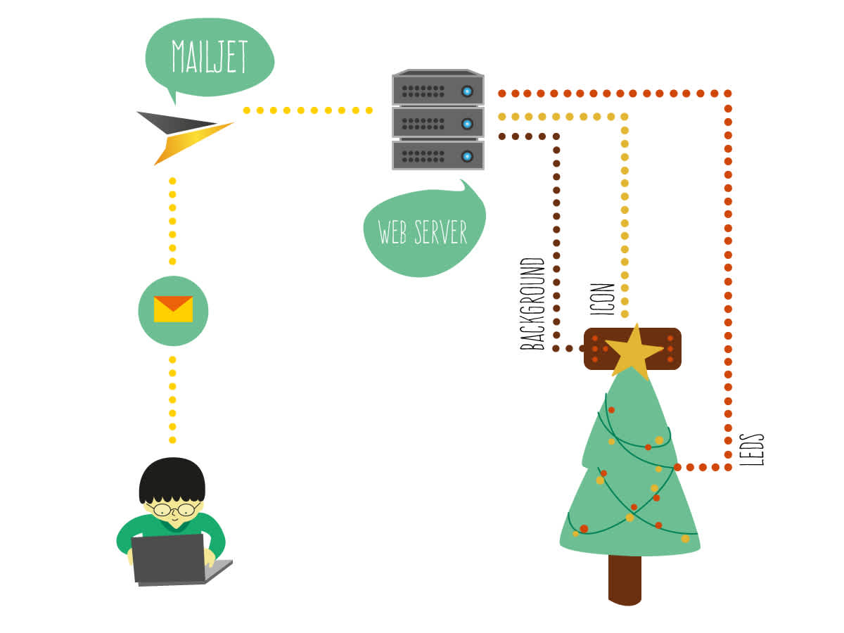
First, a person will send an email to the email address you have associated with Mailjet's Parse API. Mailjet's Parse API will then receive this email, dissect it down into it's individuals components (to, from, subject, body, etc.), and then dump the contents of that email onto the web server via a POST request.
The web server then takes the pertinent information - the commands - from the the body of the email, performs a bit more logic and formatting before it sends them over to the Spark Core via another POST request. The Spark Core receives the information and executes the functions defined in it's firmware for changing the LEDs, the dot matrix background, and icons depending on the commands it has received.
Wiring
First, I will explain how to wire the LED strip and the LED dot matrix. Then, I will explain the Spark Core software that controls each of these. Then, I will explain how to setup your Mailjet Parse API instance. Last, I will explain how to setup the web server that will accept the emails from the Parse API that then communicates with the Spark Core.
LED Strip
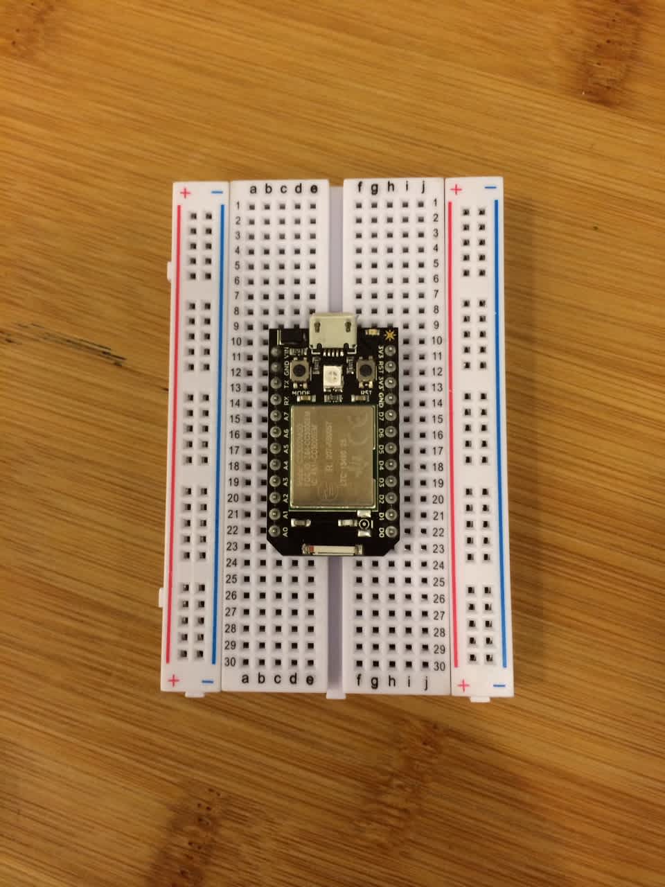
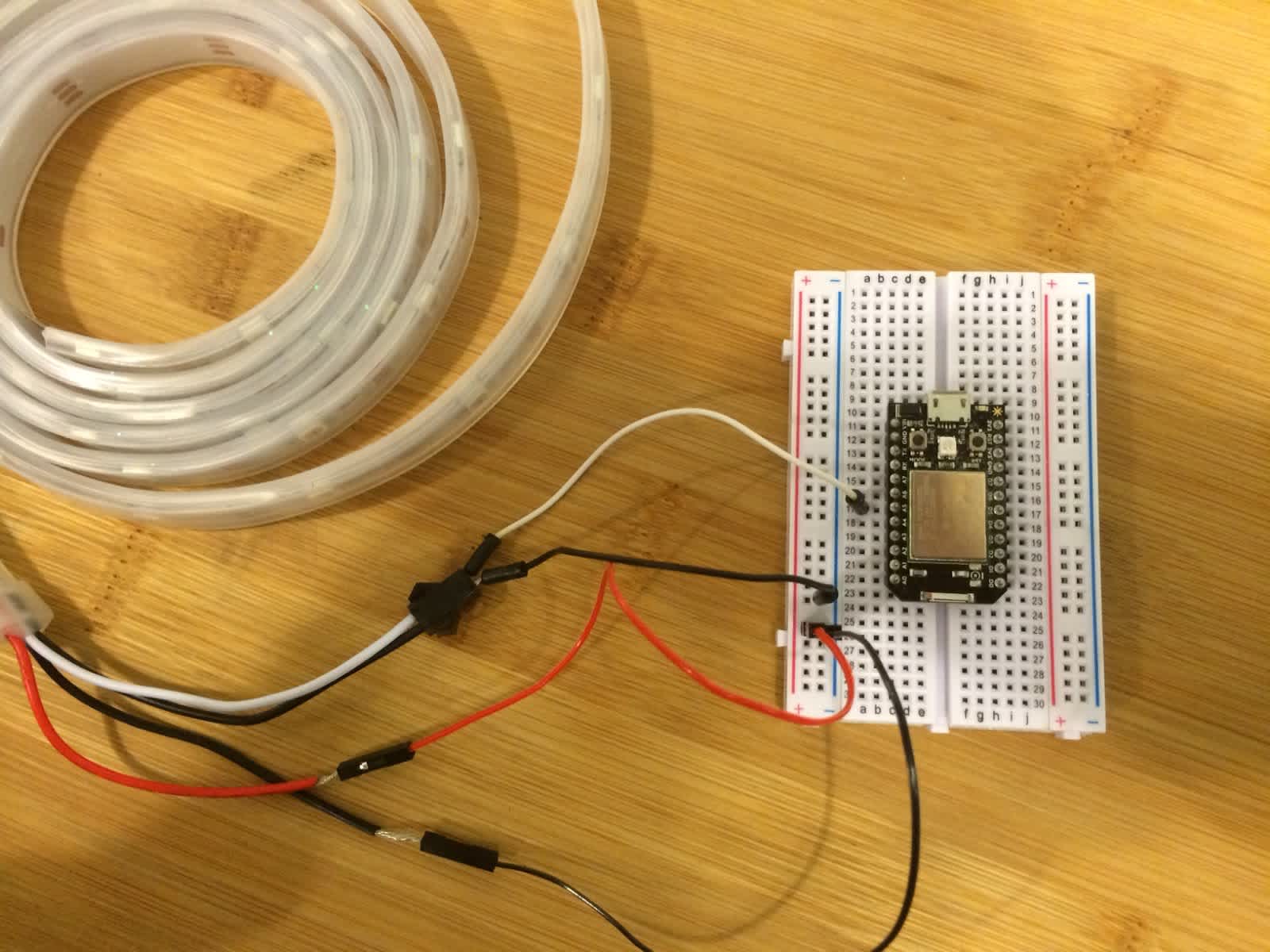
First thing's first, place the Spark Core in the middle of the your breadboard. To keep with consistency, make sure the "+" lines are always to the left of the "-".
There will be four wires coming out of the LED strip: one red, one white, and two black. The black and red wires on the left-hand side are the ground and power, respectively, lines for powering the strip. The black and white wires on the right-hand side are the ground and logic wires, respectively, for the updating the colors of the LEDs on the strip. Basically, the ones on the left make it light up and the ones on the right change the colors.

Insert the exposed wires for the power into the female end of a male-female wire. Next, insert a jumper wire into each of the logic wires.
Now, connect these to the board as such
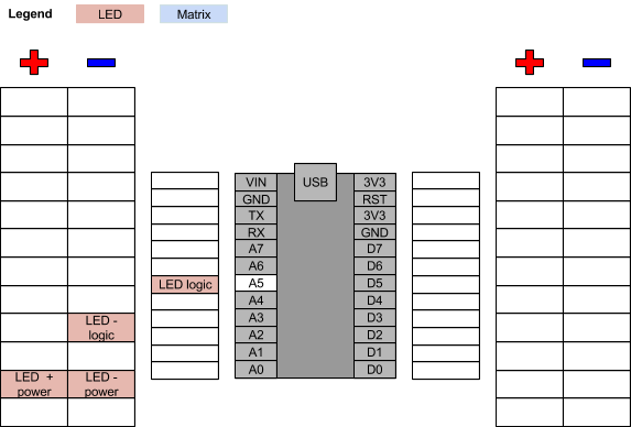
So it should now look like this:
The LED strip requires a bit more power than the onboard power supply can handle, so we will use a dedicated power supply for both this and the LED dot matrix. As per adafruit, use the following equations to estimate how much amperage you need:
lower limit for minimum Amps = number of pixels *20 mA1000 upper limit for minimum Amps = number of pixels *60 mA1000
For our, case we have:
lower limit for minimum Amps = 60*20 mA1000=1.2 Amps upper limit for minimum Amps = 60*20 mA1000=3.6 Amps
So we need 5 volts and anywhere from 1.2 amps to 3.6 amps. Good news is that we have a power supply of 5 volts and 10 amps. (Don't worry that we have 10 amps. The LEDs will only take as much current as they need. It would be a voltage higher than 5 that could damage them.)
LED Dot Matrix
Flip the dot matrix over to have a look at it. There will be a few in and out pins, but we only need two for this tutorial - logic and power. The other is for hooking up tandem dot matrices.
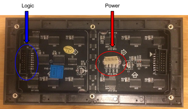
First, we'll setup the logic wiring for the dot matrix. You should have a grey cable with many holes to insert wires into. It looks like this:
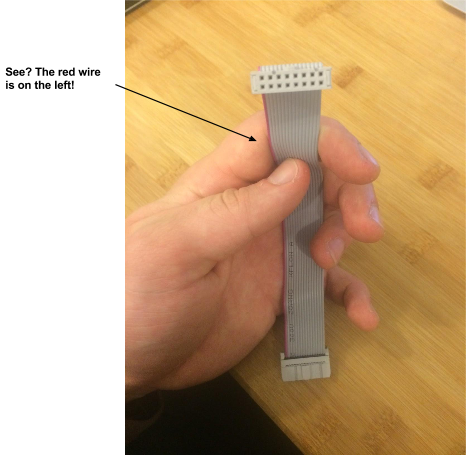
Each one of these holes corresponds to some portion of the logic that will make the dot matrix display and light up in different patterns -the amount of red/green/blue in a pixel, the timing, etc.
Using the red strip on the grey cable as a guide and always keeping it on our left hand-side, here is what each hole does and where it will wire on the Spark Core:
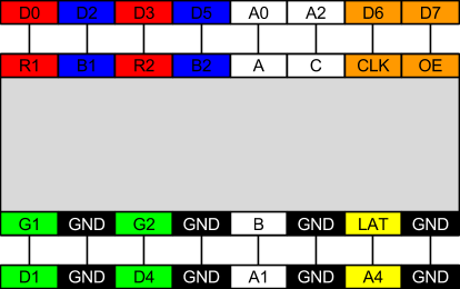
Inserting the wires into their respective slots, it will look like this:
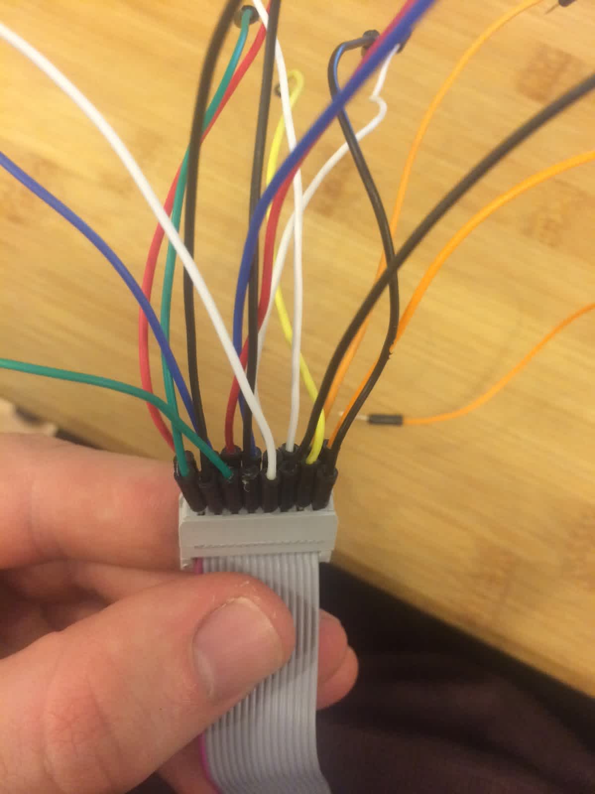
I suggest wrapping this piece in electrical tape to avoid any unintentional pulling and loosening of wires.
Now that we have all of the logic wires in place, let's hook them up to the Spark Core on the breadboard. Here is the updated diagram from before:
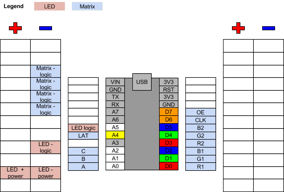
Here is what it will look like:
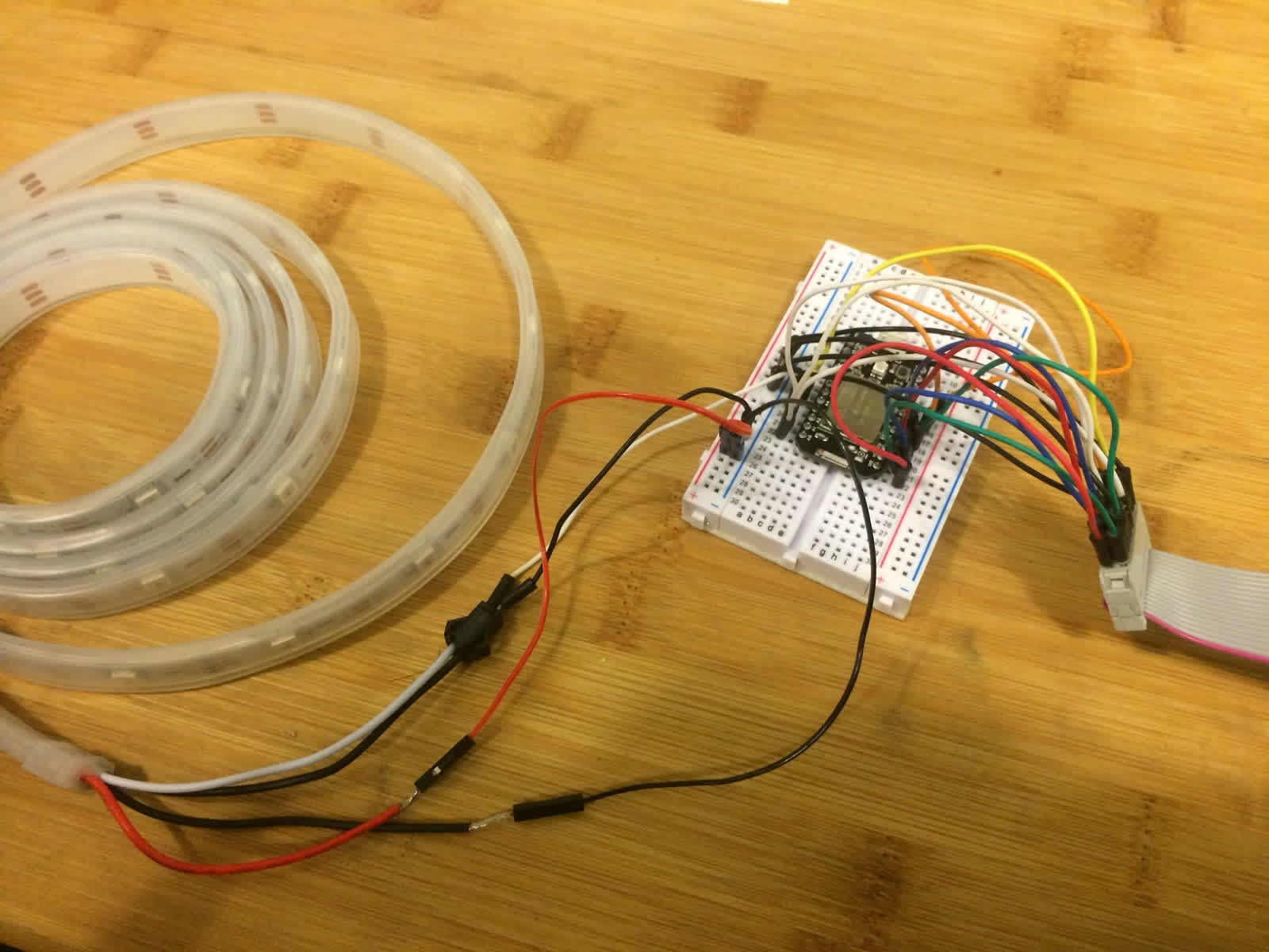
Now, connect the other end of the grey cable into the the back of the dot matrix in the port that says “IN”.
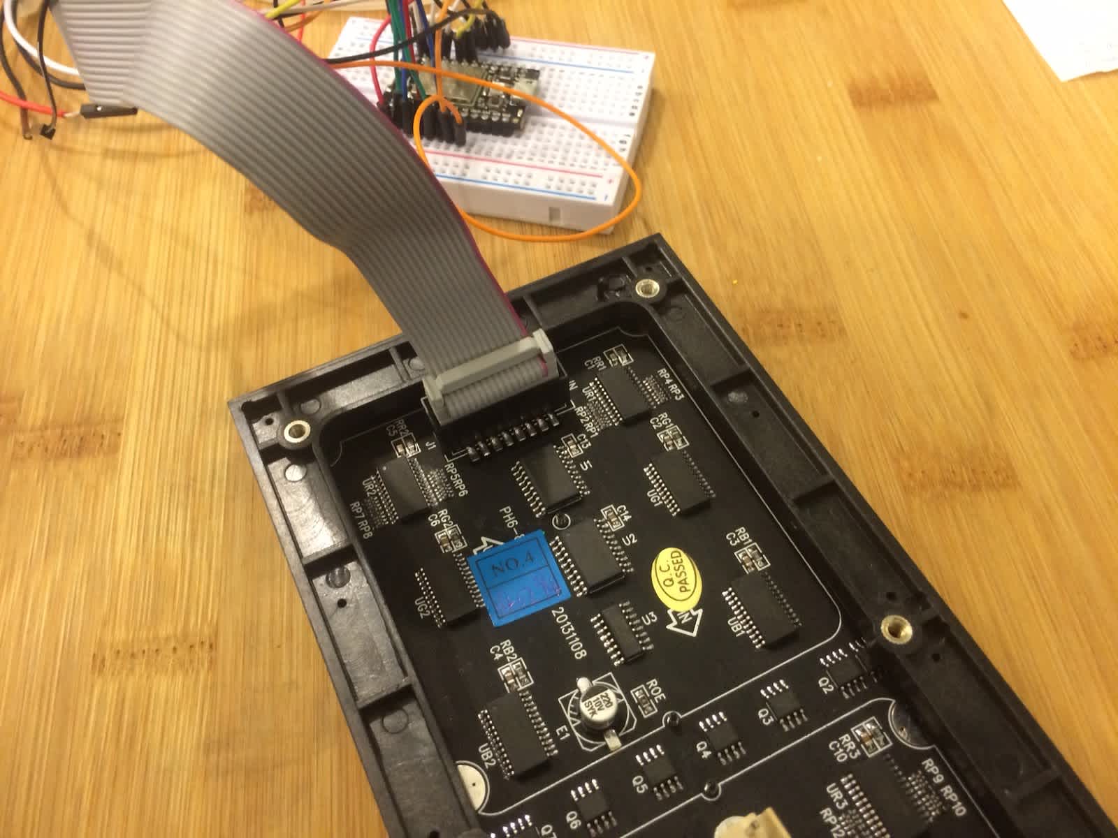
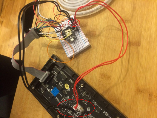
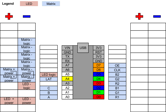
Connect the power cable into the back of the dot matrix and plug it into the breadboard. Here is what it will look like and updated wiring diagram for this:
Powering
Let there be power! (Note: during this portion, leave the power supply unplugged when wiring to the Spark Core)
The LEDs and the LED dot matrix require their own power supply. Because of this, we will use a 5 volt 10 amp power supply. In order for this to play nicely with our Spark Core and other components on the breadboard, we'll use a female DC Power adapter.
Plug the adapter into the output of the power supply, insert one wire into the positive terminal and another into the negative terminal. Tighten the screws on top with the “mini”ish screwdriver to keep them in place. I also recommend wrapping this junction in electrical tape if possible, to avoid unintentional wire pulls.
Plug the positive wire (red) into the “+” on the breadboard, and the ground wire (black) into the “-” on the breadboard.
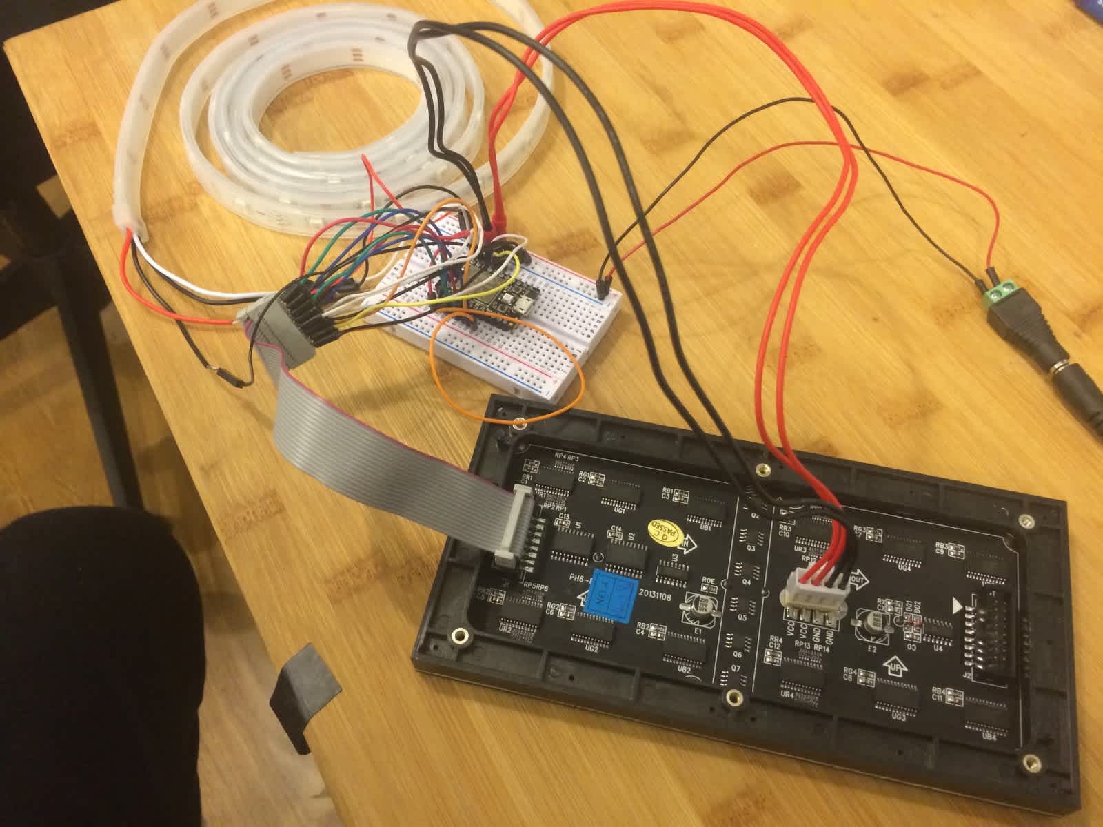
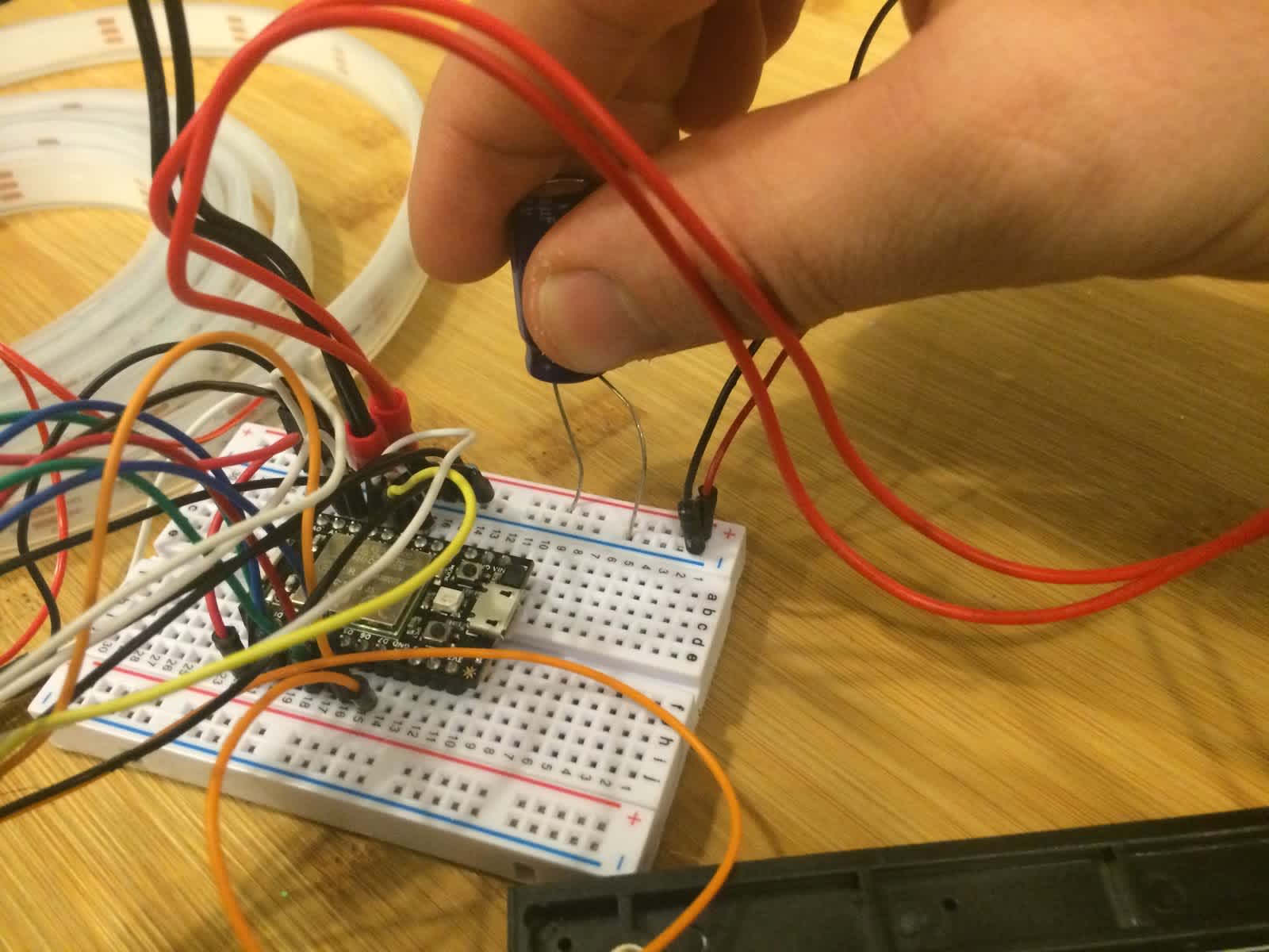
In order to protect the LED strip, we will connect a capacitor across the “+” and “-” on the breadboard. When doing this, have the long wire coming out of the capacitor in the “-” and the short wire into the “+”.
To tie everything together so that all of the components - Spark Core, LEDs, dot matrix - are on the same page, let' connect the Spark Core's ground to the “-” strip. The resulting wiring diagram is now:

The wiring should be all ready to go. You can plug it in at this time, but don't expect anything to happen just yet because we haven't uploaded any firmware to the Spark Core.
The breadboard - solderless vs permanent PCB
I would recommend prototyping and testing on a solderless breadboard first. Once you know the wiring is correct, I would move it over to a more permanent PCB (printed circuit board). The reason I say this is because these are lights on a Christmas tree, and such decorations always present a fire hazard. To take extra precaution, solder it and apply electrical tape to all exposed wires before placing everything on your tree.
Uploading the firmware
If you haven't done so already, go ahead and clone the Github repository to your computer. To do so, open your terminal, navigate to where you want to store this project, and use the following command to make a copy of the project onto your computer:
git clone https://github.com/tylernappy/email\_controlled\_christmas\_tree.git
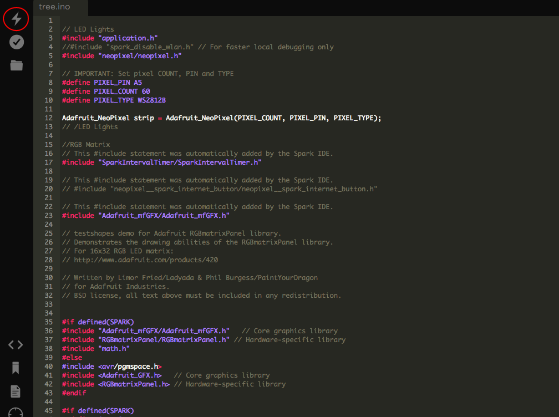
Open up the project in your favorite text editor (sublime, atom) and open the file - tree.ino - which contains the firmware (aka software) for the Spark Core. The easiest way to upload it to the Spark Core is to create a new app on the Spark Core's online IDE, copy the code from tree.ino, and paste it in there, otherwise, you can use their IDE based on the atom text editor. Then, hit the “lightning” icon to upload the firmware. On the screen, it should say at the bottom - something along the lines “uploading code, please wait.”
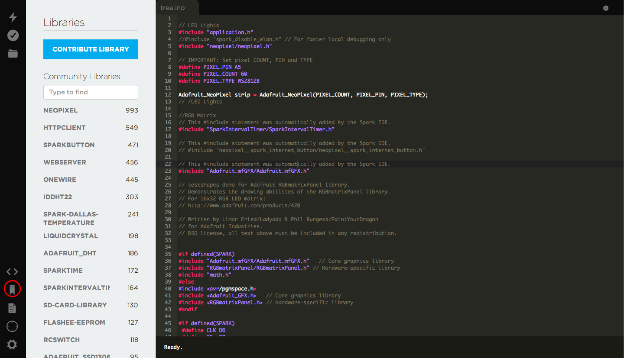
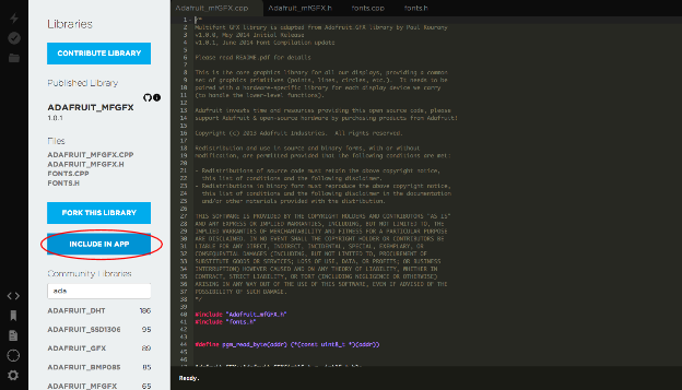
If for whatever reason an error pops up saying there is a library that isn't included, you can go in and add them manually by clicking the libraries icon, searching for the SparkIntervalTimer library and the Adafruit_mfGFX library and click "INCLUDE IN APP".
I have written the firmware to turn the lights and matrix on when the Spark Core starts up. If you see this happen, the Spark Core firmware has been uploaded correctly.
Web server
To start off, we will host the web server on your local computer for testing purposes. Once all of kinks are worked out, we will push it up to Heroku where your app will live in the ether of the internet!
Since you already have the Github repository cloned on your computer, go ahead and open up a new tab in your terminal, and "cd" in to the Rails server that came with it using the following command:
cd christmas_tree_server
Now, run the following command to run a local server:
rails server
At the moment, only you can access this web server from your computer. This won't work for us, seeing as we need Mailjet's Parse API to access your computer. To solve this, we're going to open up your computer through local tunneling via a service called ngrok (if you don't already have this set up, go to their site, download, and acquaint yourself with the service).
Open up another another tab in your terminal, "cd" to where you downloaded ngrok, and use the following command to open a local tunnel on your computer to port 3000, which the Rails server defaults to:
./ngrok 3000
You will see the following screen - this is the URL to access your server:

For this particular case, the server is at https://3cbc1861.ngrok.com. Write yours down as you will need it when setting up Mailjet's Parse API. For the rest of this tutorial, I will use http://3cbc1861.ngrok.com as the server URL but remember to use what ngrok gives you, otherwise Mailjet will deliver the emails to the wrong URL!
Specifically, we have the web server accepting POST requests from the http://3cbc1861.ngrok.com/email\_processor endpoint. If at any point you wish change the logic in the web server before the information is delivered to the Spark Core, you will find that in app/controllers/change_lights_controllers.rb.
Pushing up to Heroku
If you have already gone through this tutorial and everything is working nicely, you're going to want to host the web server in the cloud rather than on your computer. To do this, we can push our Rails server up to a service called Heroku - a web hosting service. If you don't already have a Heroku account, I would sign up and acquaint yourself with the service. It's pretty awesome and free.
Once this is up and running, remember to update the URL in your instance of Mailjet's Parse API to whatever the URL is of your Heroku app.
Mailjet's Parse API
First thing's first, we need to find your API Key and Secret Key for your Mailjet account (if you haven't already done so, sign up for Mailjet here).
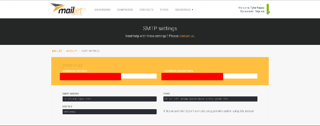
You will find them here under “Configuration (SMTP only)” on the main dashboard. Keep these secret, otherwise someone can send emails on your behalf!
Now, we're going to create an instance of the Parse API using a curl request. In terminal, paste the following, then hit enter. Remember to substitute "API_KEY" and "SECRET_KEY" with your respective credentials and http://your.webhook.com with the server URL ngrok (or Heroku) returned back to you:
curl —user "API_KEY:SECRET_KEY" https://api.mailjet.com/v3/REST/parseroute -H 'Content-Type: application/json' -d '{"Url":"http://your.webhook.com/email\_processor"}'
This command will create an instance and return back to you something like this:
{ "Count" : 1, "Data" : [{ "APIKeyID" : 123456, "Email" : "christmas-tree-app@parse-in1.mailjet.com", "ID" : 12, "Url" : "http:\/\/47c528d4.ngrok.com\/email_processor" }], "Total" : 1 }
The email returned back to you - in this case, christmas-tree-app@parse-in1.mailjet.com - is the email that when sent to, will dump all of the email contents onto your web server via a POST request. If you wish to update this email address to something a bit more aesthetic, use this command:
curl -s -X —user "API_KEY:SECRET_KEY" https://api.mailjet.com/v3/REST/parseroute -H 'Content-Type: application/json' -d '{"Email":"whatever-you-like@parse-in1.mailjet.com"}'
Decorating the tree
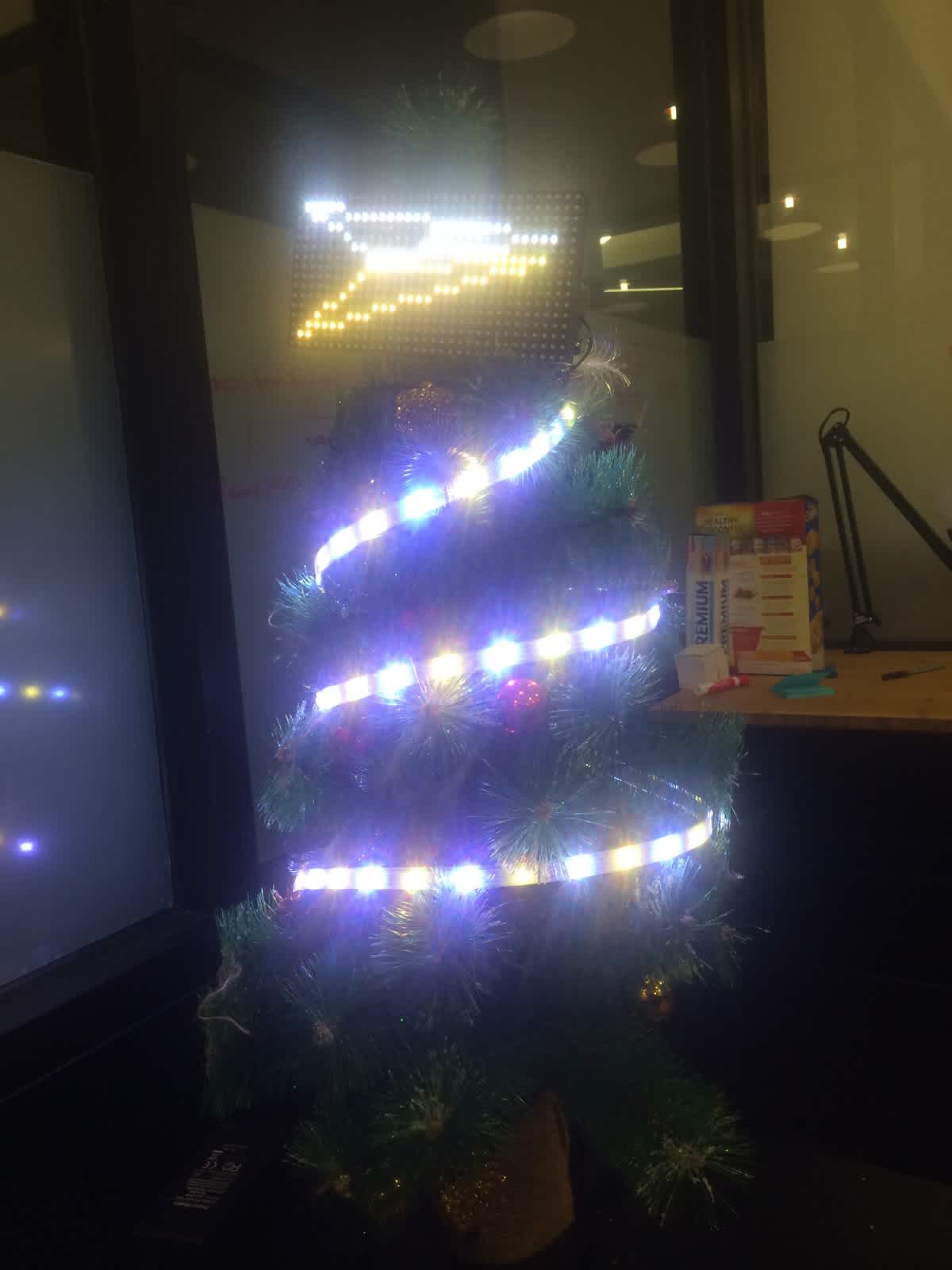
Now that you have all of the the hardware wired, all the firmware uploaded, and the server up and running, it's time to decorate the tree! From my experience, the best way to do this is to put the dot matrix at the top of the tree first and then wrap the LEDs around the tree going from top to bottom.
To mount the dot matrix at the top of the tree, I screwed in the four magnets to the back (these came with the dot matrix) , then placed the rubber band onto one of the sides, twisted the rubber band a half turn, then put the other side of the rubber band on the other side of the dot matrix - essentially creating an "X" with the rubber band that effectively mounts it to the tree.

Here is what it will look like once you're done!
Changing the lights via email
At the moment in the Github repo code, you can email up to three commands by putting them in the body of the email. The three commands are "lights", "background", and "icon".
Below is a list of all currently available options for each of the commands.
lights "lights" changes the color and pattern of the lights around the tree.
blue
green
red
christmas
mailjet
background "background" changes the background color of the display on top of tree.
blue
green
red
black
icon "icon" changes the icon on the display on top of the tree.
circle
mailjet
star
logo
Example email
The following example will change the lights blue, put a star on the display, and make the background color of the display green. Remember to change the email address you are sending to the one you have have associated with Mailjet's Parse API:

El fin
And that's it! Enjoy your email controlled Christmas tree!
If you see any bugs or wish to add more light patterns, dot matrix icons colors and icons, send me a pull request or email me at tyler@mailjet.com.
Thanks to Big Brothers Big Sisters
We're excited to say that Big Brothers Big Sisters of NYC will be taking control over the Email Controlled Christmas Tree. For those of you who don't know who they are:
Big Brothers Big Sisters of NYC serves over 3500 children finding them mentors to help ensure their success in life. We do this by partnering with families, volunteers, companies and the community to inspire a positive change in all. Visit www.bigsnyc.org to learn more about becoming a BIG or to donate towards our Education Initiative.
Help light up the holidays by donating to Big Brothers Big Sisters: https://www.bigsnyc.org/donate
Want to define your email strategy to win customers over this holiday season? Check out Mailjet's Ultimate Guide To Holiday Emailing.
By Tyler Nappy


